Spindle Shaft
From Teamnumber1
(Difference between revisions)
(→Spindle Shaft Design, 12th April) |
|||
| Line 23: | Line 23: | ||
[[Image:Shaft Bearing Constraint.jpg]] | [[Image:Shaft Bearing Constraint.jpg]] | ||
| + | |||
| + | |||
| + | ==Bearing Selection== | ||
| + | For spindle shaft bearings, we selected tapered roller bearings - see [[Bearing Selection]] for more details. | ||
Current revision as of 23:35, 11 May 2007
Contents |
Spindle Shaft Design, 7th April
- Developed a model to predict the peak cutting force and shaft torque
- Wrote a matlab tool (edited version 12th April below) to determine peak forces and bending moments in spindle shaft and bearings
- Wrote a matlab tool to specify bearing from cutting force, torque, and desired life and reliability (via the Weibull Equation)
- Specified a collet from sheets provided in lab
- Used results from above tools and supplied lathe solid model to specify shaft dimensions:
- 30 mm shaft outer diameter, 50mm diameter for center section
- 10 mm inner diameter
Spindle Shaft Design, 12th April
- Altered matlab tool to take into account fatigue at bearing A.
- For a steel shaft, we have a slope factor of safety of 9, a stress factor of safety of 15. The stresses are an order of magnitude below the endurance limit, so fatigue should not occur anywhere in this shaft. (or, a lifetime of 10^10 minutes - about right according to Chris).
- Assumptions - w_shaft = 570rpm, axial force = 100N, radial force = 240N, stress concentration at fillet = 2.5, assume 1020 steel which is pretty weak.
- Endurance limit of 1020 steel = 210MPa, k_overall=0.75, Von Mises stress at Bearing A = 21.6MPa, and smaller at nut by rough calculation.
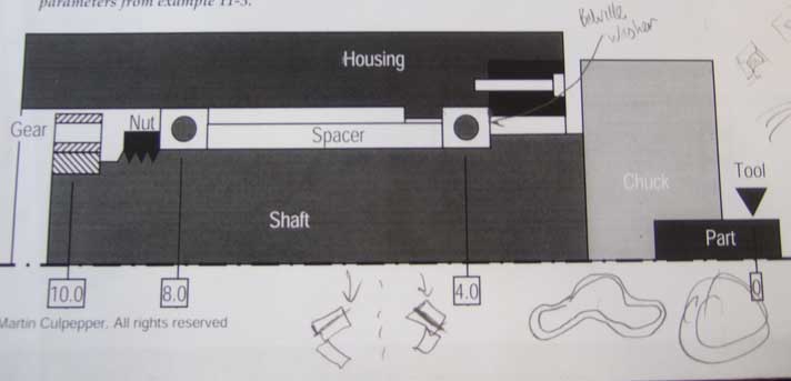
Spindle Shaft Bearing Constraint
As discussed with Chris 4/26 - Martin & Ani
Bearing Selection
For spindle shaft bearings, we selected tapered roller bearings - see Bearing Selection for more details.


