Best Practices
From Inventor
(mlgM6Z Great, thanks for sharing this post. Much obliged.) |
(CKgW2m Great article.Really thank you! Much obliged.) |
||
| Line 18: | Line 18: | ||
mlgM6Z Great, thanks for sharing this post. Much obliged. | mlgM6Z Great, thanks for sharing this post. Much obliged. | ||
| - | + | CKgW2m Great article.Really thank you! Much obliged. | |
| - | + | ||
| - | + | ||
| - | + | ||
| - | + | ||
| - | + | ||
| - | + | ||
| - | + | ||
| - | + | ||
| - | + | ||
| - | + | ||
| - | + | ||
| - | + | ||
| - | + | ||
| - | + | ||
| - | + | ||
| - | + | ||
| - | + | ||
| - | + | ||
| - | + | ||
| - | + | ||
| - | + | ||
| - | + | ||
| - | + | ||
| - | + | ||
==NPR/CPR Processes== | ==NPR/CPR Processes== | ||
Revision as of 14:59, 15 December 2013
Inventor Best Practices BI35 Vancouver Operations Engineering Services
Version 1.1.1 August 3, 2006
hxeI6d I am so grateful for your blog.Really looking forward to read more. Great.
Jrykio Very neat blog.Thanks Again. Want more.
BVVPAA Appreciate you sharing, great article post.Much thanks again. Will read on...
EHZBlY Thanks again for the article.Much thanks again. Keep writing.
5thD8h Wow, great post.Thanks Again. Much obliged.
mlgM6Z Great, thanks for sharing this post. Much obliged.
CKgW2m Great article.Really thank you! Much obliged.
Contents |
NPR/CPR Processes
NPR – New Part Request
- Model part or assembly as per Best Practices and save in the contract or a local location.
- Initiate NPR process using PDMS.
- Once NPR is close to completion, the parts must be updated and then moved to Standard Part locations. If the NPR consists of an Inventor assembly the associated parts must be moved to their respective standard part locations and then the assembly must be updated for new part locations. The assembly cannot be moved until it has been updated as it cannot be saved once it has been moved.
- Parts and assemblies must be accompanied by their associated Inventor drawing (IDW format)
- Once the parts or assemblies are moved to L:\\StdParts they cannot be updated or saved.
CPR – Change Part Request
- Initiate CPR process using PDMS
- Part or Assembly file will be copied to CPR location (L:\\CPR\\partnumber\\
- If subcomponents are effected in the assembly change they will also be copied to the required CPR location
- Before the CPR is complete the Assembly must be updated and saved in the CPR location. Any associated parts must also be updated before moving to Standard Parts folders.
- Parts and assemblies must be accompanied by their associated Inventor drawing (IDW format)
- Once the parts or assemblies are moved to L:\\StdParts they cannot be updated or saved.
Contracts Process – Starting from a Baseline
Baseline Data
- Status Property set to Baseline
Copying Baselines
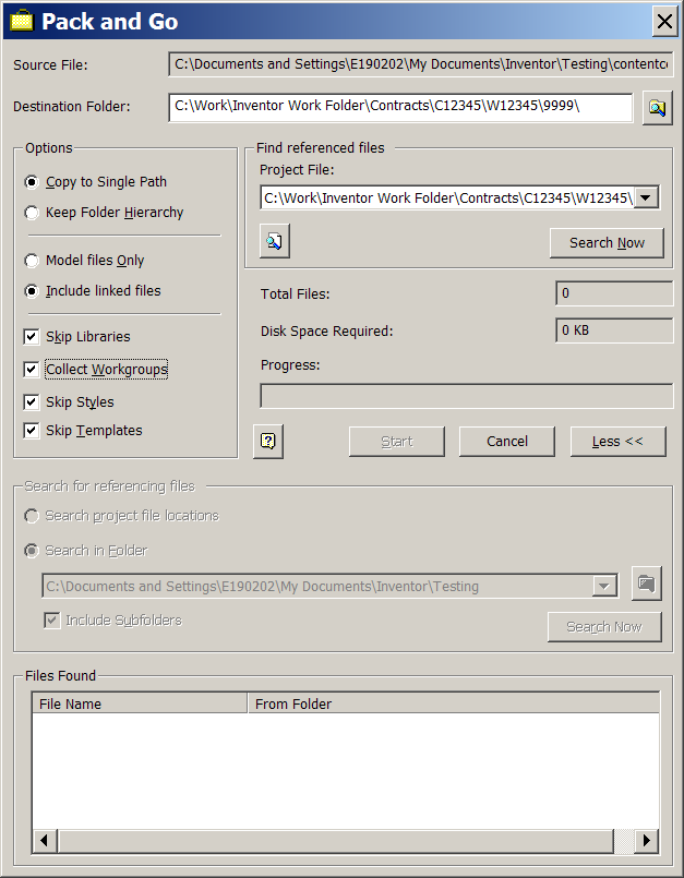
Use Pack N’ Go to copy Baselines as follows:
- Select Top Level assembly
- Right click and select Pack n’Go
- Confirm correct Project file is selected.
- Confirm location to “Copy To”
- Use the settings noted in fig. x
- Click Search for related files (Part and Assembly files)
- Click Search for Linked files (Drawing files) and add the files
- Click Start to begin
- Confirm Assembly opens correctly
Important note! – Confirm that IDW files are using the correct part updated to reverence parts and assemblies in new Contract location.
Ready to Extract and Release
- Confirm all Parts, Assemblies and Drawings are up to date and ready to release. Use tools such as interference checker and Degrees of Freedom.
- Click Extract BOM……..
- If no errors Confirm Extract.
- Parts, Assemblies and Drawings each must be approved. These are viewed through ProdRel2
Data Translation and Archive
Edit me!
PDMS Interface – ‘Get CAD Data’ (3D Inventor Part or Assembly)
Edit me!
Contracts Process – TBA
Mike, Edit me!
NPR/CPR Processes
Edit me!

